***
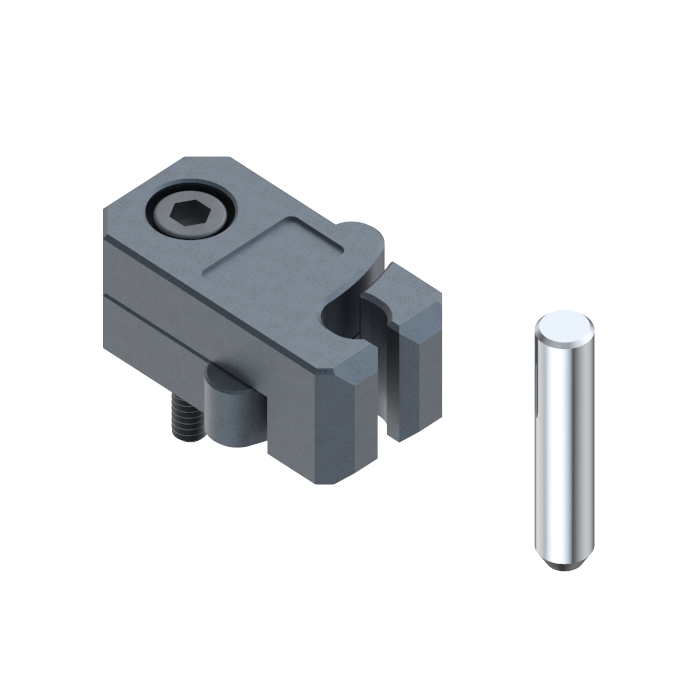
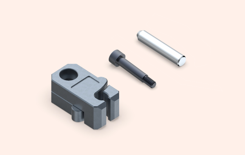
Y-psm-psm Slide Limit clamp - American standard metric Slide limit clamp Slide position limit retain
Specification
- Detail
- Parameters
- Review

| Model/Specification | A | B | C | D | E | F | N | T | U | G | H | J | R | M | D1 | L |
Y-PSL0001 | 1.50 | 0.76 | 0.63 | 0.27 | 1.23 | 0.980 | 0.94 | 0.250 | 1.25 | 1.35 | 0.39 | 1.00 | 0.31 | #10-24 | 0.249 | 0.31 |
Y-PSL0002 | 2.13 | 1.26 | 0.79 | 0.44 | 1.69 | 1.375 | 1.44 | 0.312 | 1.50 | 1.81 | 0.56 | 1.50 | 0.37 | 1/4-20 | 0.312 | 0.43 |
Y-PSL0003 | 3.38 | 1.76 | 1.18 | 0.75 | 2.63 | 2.125 | 1.94 | 0.375 | 2.25 | 2.75 | 0.88 | 2.00 | 0.50 | 5/16-18 | 0.374 | 0.58 |
Specification | Maximum clamping force(Kgf) |
Y-PSL0001 | 10 |
Y-PSL0002 | 20 |
Y-PSL0003 | 40 |
Installation instructions:
During installation, there must be a clearance between the screws and the main body, and the main body must not be locked so that the limit clamp can rotate freely.
The slider stroke must be accurately calculated and processed. If the stroke is exceeded, the limit clamp may be damaged.
If multiple limit clips are used for fixation, attention should be paid to the force balance of the limit clips.
价格
***
Stock
6000